After receiving several requests for a how to build an ATO I put together some instructions tonight.
< ="text/">
Bill of Materials
One
12 Volt DPDT Relay (Ebay, Radio Shack, etc.)
One
small project box to house relay and 110 VAC wire junctions (Radio
Shack)
Two
float switches (Marine Depot or BRS)
Two
plastic medicine bottles to house the switches (the medicine chest)
One
12 VAC power supply (I used a cell phone wall charger, the output
voltage is on the label)
Small
submersible pump (Harbor Freight)
Tubing
to fit the pump's outlet and of a length to go from your ATO
reservoir to the spot in your sump where you want the ATO to feed
(Lowe's)
Short
extension cord with the proper plugs for your pump (some require two,
hot and neutral; others require three, hot, neutral and a ground)
Electrical
shrink tape (helps keep the water out and looks more professional)
Wire
ties and some egg crate
Tools
Drill
and bits
Wire
cutters with wire stripper
Razor
knife
Wire
connectors and tape (if you don't solder them and use shrink tape)
Soldering
iron and LEAD solder with rosin core
Determine
where you want to mount the relay box to keep if out of the way and
protect it from getting damp
Determine
the routine of the extension chord from the outlet to the ATO pump
location in your reservoir
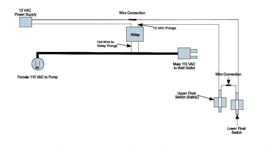
At
the point on the extension cord where the relay box will go, slice
the outer skin of the cord. Two wire cord my not be marked with
different color wires, but select the one that goes to the hot side
of the plug. On a three wire cord select the black wire (hot). Once
you have separated the wires cut the hot wire and strip it back 3/8
inch. Solder or use push connectors to attach both pieces of the hot
wire to the 110 normally closed prongs on the relay.
Drill
hole in the sides of your bottles to allow water to enter and exit.
Drill a hole in each cap and mount the float switches with the wires
outside the top.
Connect
one wire from each of the float switches together. This should join
the two switches and leave you with one wire coming off each. The
switches don't have a polarity so it doesn't matter which wire you
use. Connect one of the two remaining wires to the 12 VAC prong on
the relay, solder or use push connectors. The other float switch
wire is connected to one of the wires on the 12 VAC power supply.
Don't forget to put the shrink tape on the wire before you connect
them, I like to solder them, but you can use pinch connectors of the
correct size. This leaves you with one wire from the 12 VAC power
supply. This wire is connected to the other 12 VAC prong on the
relay,
Mount
your bottles to a piece of egg crate at the correct height for the
ATO to turn on with wire ties. Make sure they don't interfere with
the movement of the float switch. Now mount one about an inch
higher. Place the caps (with the float switches and wiring
attached) on the bottles. Place it on the sump and secure it from
moving. I use a small plastic clamp and clamp it to the side of the
sump. Plug in our power supply and extension cord. Place the tubing
on the pump and plug the pump into the female fixture on the
extension cord. Put the pump in the ATO reservoir. Now adjust the
height of the bottles the switches are in to get the correct level
to
turn on the switches.
Route
the feed tube to the correct location in the sump and secure it with
wire ties so that the outlet is above the highest water level. This
will prevent the ATO from siphoning water from the sump back into
the ATO reservoir when it shuts down. This is pretty important
since you can overflow the ATO reservoir or if it only back siphons
a small amount it will likely trip the float switch and cause the
pump to come on again in a continuing cycle of fill, back siphon
which lowers the water level enough to cause the pump to start
again, renewing the cycle over and over.
I
like to check the relay with a multimeter to ensure I have the
correct prongs before connecting the wires. You can touch the 12 VAC
leads to the proper prongs on the relay and hear it switch. Leave
them on and connected and check with the Ohms meter for the correct
set of 110 prongs. They should have continuity with the 12 VAC
connected. When the 12 VAC supply is removed the 110 prongs should be
open.
Be
cautious, water and household voltage can create a dangerous
combination. Ensure all wires and connections are not in the water or
where water will drip.
Wiring
diagram
Edited by Fatman - December 30 2012 at 10:36am


 Topic Options


 Post Options
") Thanks(0)
Thanks(0)


